| sprzedawcę | Numer części | Producent | Szczegółowy opis | Price | Qty.
BuyNow |

PUI | VP01EP
| | | | 4
 |

Pasternack Enterprises US | PEMACTRF8P01
| Pasternack Enterprises | Key Specifications Contact Size 8 Contact Series BMA Contact Gender Pin Max Frequency 22 GHz VSWR 1.35:1 Attachment Solder/Non-Solder Contact MIL-STD Types D38999 Series I, D38999 Series III and D38999 Series IV. BMA Pin Size 8 D38999 Contact for 0.085 Cable, 22 GHz Max Frequency. The PEMACTRF8P01 from Pasternack is a size 8 BMA pin contact that is designed for D38999 Series I, D38999 Series III, and D38999 Series IV military type connector shells. This RF coaxial contact has a solder/non-solder contact attachment method and is built to offer superior performance in demanding applications that require high-frequency data transmission. The BMA coax contact comes with an impedance of 50 Ohms and a maximum VSWR of 1.35. Our RF contact has a maximum frequency of 22 GHz. This BMA RF contact is made up of stainless steel material with gold plating. The PEMACTRF8P01 coax contact has a PTFE dielectric type and a dielectric withstanding voltage of 1000 Vrms. Our BMA pin contact has a maximum insertion loss of 0.375 dB. Pasternack’s RF contact has an inner conductor material constructed of beryllium copper and an outer conductor material of stainless steel. These RF coax contacts are specifically engineered to minimize signal loss and crosstalk, providing excellent impedance matching and reducing VSWR. Our BMA pin contact can operate at temperatures ranging from -65 to 165 degrees C. PEMACTRF8P01 RF contact is part of more than one million RF, microwave, and millimeter wave parts in stock at Pasternack. This PEMACTRF8P01 coax contact is ready to buy and can be shipped worldwide the same business day as ordered from our warehouse in the United States. Pasternack maintains BMA pin RF contacts in various sizes and configurations, which allows them to be customized to meet the specific requirements of different applications. For further information on similar products, our expert technical support and trained sales team can get you the ideal RF contact as per your requirements. Features Fits any MIL-DTL-38999 size 8 insert Superior high frequency performance Blindmate connections Made from high quality materials giving a robust mechanical design Solderless inner connection to reduce assembly cost Applications Civilian and Military Aerospace High Reliability Installations Harsh Environments. | 1 : $33.89
25 : $32.2
50 : $30.5
100 : $29.15
|
| 46
 |
PE2CP019
| Pasternack Enterprises | | 1 : $436.99
10 : $419.51
25 : $402.03
|
| 21
|
FMW28CP010-20
| Pasternack Enterprises | | 1 : $2,590.0
5 : $2,486.4
10 : $2,382.8
25 : $2,279.2
|
| 15
|
PEWRD180CP01-30
| Pasternack Enterprises | Key Specifications, Waveguide Size : WRD-180, Flange Type : Cover Flange, Flange Group : Standard, Minimum Frequency: 18 GHz, Maximum Frequency: 40 GHz, Impedance : 50 Ohms, Maximum VSWR: 1.6:1, Maximum Insertion Loss: 0.5 dB, Coupling: 30 dB. WRD-180 Double Ridge Waveguide 30 dB Broadwall Coupler, 2.92mm Female Coupled Port, 18 GHz to 40 GHz, Brass., Pasternack’s PEWRD180CP01-30 is a WRD-180 directional broadwall waveguide coupler with a 50 Ohm impedance. This directional waveguide coupler has an 2.92MM connector with a female gender configuration for the coupling port. Our waveguide coupler operates over a frequency range between 18 GHz and 40 GHz. The PEWRD180CP01-30 WRD-180 waveguide coupler is a great option for test benches, radar, satellite, microwave radio, attenuation measurements, power measurements and source leveling applications. This waveguide broadwall coupler is designed with an coupled port and has a coupling accuracy of 30 dB. The PEWRD180CP01-30 broadwall waveguide coupler from Pasternack is designed with a coupling value of 30 dB and 2 dB coupling flatness. This 30 dB waveguide coupler has a brass body with gray plating. Our WRD-180 directional waveguide coupler is rated for a maximum input power (CW) of 250 Watts. This 40 GHz waveguide coupler has a 1.25:1 maximum main line VSWR (voltage standing wave ratio). Additional dimensions and specifications for this WRD-180 waveguide coupler are on our downloadable PDF datasheet above. This directional waveguide coupler has 1,000 Watts of peak power along with a directivity of 20 dB. The PEWRD180CP01-30 broadwall waveguide coupler from Pasternack is frequently used in situations where power measurements are necessary within a system for measuring/sampling power or frequency monitoring with minimal signal loss to the main transmission line. Our 250 Watts (CW) waveguide coupler has a maximum insertion loss of 0.5 dB. This WRD-180 waveguide coupler is one of the thousands of products available from Pasternack’s in-stock inventory with same business day shipment for local, domestic, and international orders. Make your online purchase for our high-quality waveguide coupler and take advantage of the same business day shipping services. For further information on similar products, our expert technical support and knowledgeable sales team can help you get the ideal directional broadwall waveguide coupler for your requirement. | 1 : $5,960.0
5 : $5,840.8
10 : $5,721.6
25 : $5,602.4
|
| 3
|
PE2CP013
| Pasternack Enterprises | | 1 : $457.99
10 : $439.67
25 : $421.35
|
| 3
|
PE-W10CP011-30
| Pasternack Enterprises | Key Specifications, Waveguide Size : WR-10, Flange Size: UG-387/U-M Flange, Flange Type : Round Cover Flange, Flange Group : Standard, Minimum Frequency: 90 GHz, Maximum Frequency: 110 GHz, Maximum VSWR: 1.25:1, Maximum Insertion Loss: 0.8 dB, Coupling: 30 dB. WR-10 Waveguide 30 dB Broadwall Coupler, UG-387/U-Mod Round Cover Flange, H-Plane Coupled Port, 90 GHz to 110 GHz, Brass Copper., Pasternack’s PE-W10CP011-30 is a WR-10 directional broadwall waveguide coupler. Our waveguide coupler operates over a frequency range between 90 GHz and 110 GHz. This waveguide broadwall coupler is designed with an H-plane coupled port and has a coupling accuracy of 30 dB. This 30 dB waveguide coupler has a brass copper body with gold plating. Our WR-10 directional waveguide coupler is rated for a maximum input power (CW) of 10 Watts. This 110 GHz waveguide coupler has a 1.15:1 maximum main line VSWR (voltage standing wave ratio). Additional dimensions and specifications for this 3-port WR-10 waveguide coupler are on our downloadable PDF datasheet above. The PE-W10CP011-30 broadwall waveguide coupler from Pasternack is frequently used in situations where power measurements are necessary within a system for measuring/sampling power or frequency monitoring with minimal signal loss to the main transmission line. Our waveguide coupler has a maximum insertion loss of 0.8 dB. This waveguide coupler has a UG-387/U-M round cover flange, which is made up of brass copper material with a gold plating. The waveguide coupler with a UG-387/U-M round cover flange has a minimum coupler directivity of 25 dB. This WR-10 waveguide coupler is one of the thousands of products available from Pasternack’s in-stock inventory with same-business-day shipment for local, domestic, and international orders. Make your online purchase for our high-quality waveguide coupler and take advantage of the same business day shipping services. For further information on similar products, our expert technical support and knowledgeable sales team can help you get the ideal 3-port directional broadwall waveguide coupler for your requirement. | 1 : $3,710.0
5 : $3,635.8
10 : $3,561.6
25 : $3,487.4
|
| 2
|
PEW22CP010-40
| Pasternack Enterprises | Key Specifications. Flange Type UG Cover Flange Flange Group Standard Minimum Frequency 33 GHz Maximum Frequency 50 GHz Maximum VSWR 1.25:1 Maximum Insertion Loss 0.4 dB Coupling 40 dB. WR-22 Waveguide 40 dB Broadwall Coupler, UGCover Flange, 33 GHz to 50 GHz, Copper. The PEW22CP010-40 is a WR-22 Directional Broadwall waveguide coupler with WR-22 coupled port that operates in thefrequency range of 33 to 50 GHz. This Waveguide component has a maximum VSWR of 1.25:1. These designs are madeof copper alloy and incorporate a broad wall configuration that result in a mid-band nominal coupling value of 10, 20, 30, 40or 50 dB. Common applications for this component would be where power measurements are required within a system formeasuring/sampling power or frequency monitoring with minimal signal loss to the main transmission line. Pasternack offersa complete family of waveguide Crossguide and Broadwall couplers that are in-stock and ship same day. | 1 : $4,350.0
5 : $4,263.0
10 : $4,176.0
25 : $4,089.0
|
| 2
|
PE-W12CP011-20
| Pasternack Enterprises | Key Specifications, Waveguide Size : WR-12, Flange Size: UG-387/U Flange, Flange Type : Round Cover Flange, Flange Group : Standard, Minimum Frequency: 60 GHz, Maximum Frequency: 90 GHz, Maximum VSWR: 1.25:1, Maximum Insertion Loss: 0.7 dB, Coupling: 20 dB. WR-12 Waveguide 20 dB Broadwall Coupler, UG-387/U Round Cover Flange, H-Plane Coupled Port, 60 GHz to 90 GHz, Brass Copper., Pasternack’s PE-W12CP011-20 is a WR-12 directional broadwall waveguide coupler. Our waveguide coupler operates over a frequency range between 60 GHz and 90 GHz. This waveguide broadwall coupler is designed with an H-plane coupled port and has a coupling accuracy of 20 dB. This 20 dB waveguide coupler has a brass copper body with gold plating. Our WR-12 directional waveguide coupler is rated for a maximum input power (CW) of 15 Watts. This 90 GHz waveguide coupler has a 1.15:1 maximum main line VSWR (voltage standing wave ratio). Additional dimensions and specifications for this 3-port WR-12 waveguide coupler are on our downloadable PDF datasheet above. The PE-W12CP011-20 broadwall waveguide coupler from Pasternack is frequently used in situations where power measurements are necessary within a system for measuring/sampling power or frequency monitoring with minimal signal loss to the main transmission line. Our waveguide coupler has a maximum insertion loss of 0.7 dB. This waveguide coupler has a UG-387/U round cover flange, which is made up of brass copper material with a gold plating. The waveguide coupler with a UG-387/U round cover flange has a minimum coupler directivity of 25 dB. This WR-12 waveguide coupler is one of the thousands of products available from Pasternack’s in-stock inventory with same-business-day shipment for local, domestic, and international orders. Make your online purchase for our high-quality waveguide coupler and take advantage of the same business day shipping services. For further information on similar products, our expert technical support and knowledgeable sales team can help you get the ideal 3-port directional broadwall waveguide coupler for your requirement. | 1 : $3,510.0
5 : $3,439.8
10 : $3,369.6
25 : $3,299.4
|
| 2
|
PEWRD650CP01-40
| Pasternack Enterprises | Key Specifications, Waveguide Size : WRD-650, Flange Type : Cover Flange, Flange Group : Standard, Minimum Frequency: 6.5 GHz, Maximum Frequency: 18 GHz, Impedance : 50 Ohms, Maximum VSWR: 1.5:1, Maximum Insertion Loss: 0.3 dB, Coupling: 40 dB. WRD-650 Double Ridge Waveguide 40 dB Broadwall Coupler, SMA Female Coupled Port, 6.5 GHz to 18 GHz, Brass., Pasternack’s PEWRD650CP01-40 is a WRD-650 directional broadwall waveguide coupler with a 50 Ohm impedance. This directional waveguide coupler has an SMA connector with a female gender configuration for the coupling port. Our waveguide coupler operates over a frequency range between 6.5 GHz and 18 GHz. The PEWRD650CP01-40 WRD-650 waveguide coupler is a great option for test benches, radar, satellite, microwave radio, attenuation measurements, power measurements and source leveling applications. This waveguide broadwall coupler is designed with an coupled port and has a coupling accuracy of 40 dB. The PEWRD650CP01-40 broadwall waveguide coupler from Pasternack is designed with a coupling value of 40 dB and 2 dB coupling flatness. This 40 dB waveguide coupler has a brass body with gray plating. Our WRD-650 directional waveguide coupler is rated for a maximum input power (CW) of 400 Watts. This 18 GHz waveguide coupler has a 1.25:1 maximum main line VSWR (voltage standing wave ratio). Additional dimensions and specifications for this WRD-650 waveguide coupler are on our downloadable PDF datasheet above. This directional waveguide coupler has 3,000 Watts of peak power along with a directivity of 20 dB. The PEWRD650CP01-40 broadwall waveguide coupler from Pasternack is frequently used in situations where power measurements are necessary within a system for measuring/sampling power or frequency monitoring with minimal signal loss to the main transmission line. Our 400 Watts (CW) waveguide coupler has a maximum insertion loss of 0.3 dB. This WRD-650 waveguide coupler is one of the thousands of products available from Pasternack’s in-stock inventory with same business day shipment for local, domestic, and international orders. Make your online purchase for our high-quality waveguide coupler and take advantage of the same business day shipping services. For further information on similar products, our expert technical support and knowledgeable sales team can help you get the ideal directional broadwall waveguide coupler for your requirement. | 1 : $5,410.0
5 : $5,301.8
10 : $5,193.6
25 : $5,085.4
|
| 2
|
PEWRD750CP01-40
| Pasternack Enterprises | Key Specifications, Waveguide Size : WRD-750, Flange Type : Cover Flange, Flange Group : Standard, Minimum Frequency: 7.5 GHz, Maximum Frequency: 18 GHz, Impedance : 50 Ohms, Maximum VSWR: 1.5:1, Maximum Insertion Loss: 0.3 dB, Coupling: 40 dB. WRD-750 Double Ridge Waveguide 40 dB Broadwall Coupler, SMA Female Coupled Port, 7.5 GHz to 18 GHz, Brass., Pasternack’s PEWRD750CP01-40 is a WRD-750 directional broadwall waveguide coupler with a 50 Ohm impedance. This directional waveguide coupler has an SMA connector with a female gender configuration for the coupling port. Our waveguide coupler operates over a frequency range between 7.5 GHz and 18 GHz. The PEWRD750CP01-40 WRD-750 waveguide coupler is a great option for test benches, radar, satellite, microwave radio, attenuation measurements, power measurements and source leveling applications. This waveguide broadwall coupler is designed with an coupled port and has a coupling accuracy of 40 dB. The PEWRD750CP01-40 broadwall waveguide coupler from Pasternack is designed with a coupling value of 40 dB and 2 dB coupling flatness. This 40 dB waveguide coupler has a brass body with gray plating. Our WRD-750 directional waveguide coupler is rated for a maximum input power (CW) of 400 Watts. This 18 GHz waveguide coupler has a 1.25:1 maximum main line VSWR (voltage standing wave ratio). Additional dimensions and specifications for this WRD-750 waveguide coupler are on our downloadable PDF datasheet above. This directional waveguide coupler has 3,000 Watts of peak power along with a directivity of 20 dB. The PEWRD750CP01-40 broadwall waveguide coupler from Pasternack is frequently used in situations where power measurements are necessary within a system for measuring/sampling power or frequency monitoring with minimal signal loss to the main transmission line. Our 400 Watts (CW) waveguide coupler has a maximum insertion loss of 0.3 dB. This WRD-750 waveguide coupler is one of the thousands of products available from Pasternack’s in-stock inventory with same business day shipment for local, domestic, and international orders. Make your online purchase for our high-quality waveguide coupler and take advantage of the same business day shipping services. For further information on similar products, our expert technical support and knowledgeable sales team can help you get the ideal directional broadwall waveguide coupler for your requirement. | 1 : $5,410.0
5 : $5,301.8
10 : $5,193.6
25 : $5,085.4
|
| 2
|
PE-W10CP011-20
| Pasternack Enterprises | Key Specifications, Waveguide Size : WR-10, Flange Size: UG-387/U-M Flange, Flange Type : Round Cover Flange, Flange Group : Standard, Minimum Frequency: 90 GHz, Maximum Frequency: 110 GHz, Maximum VSWR: 1.25:1, Maximum Insertion Loss: 0.8 dB, Coupling: 20 dB. WR-10 Waveguide 20 dB Broadwall Coupler, UG-387/U-Mod Round Cover Flange, H-Plane Coupled Port, 90 GHz to 110 GHz, Brass Copper., Pasternack’s PE-W10CP011-20 is a WR-10 directional broadwall waveguide coupler. Our waveguide coupler operates over a frequency range between 90 GHz and 110 GHz. This waveguide broadwall coupler is designed with an H-plane coupled port and has a coupling accuracy of 20 dB. This 20 dB waveguide coupler has a brass copper body with gold plating. Our WR-10 directional waveguide coupler is rated for a maximum input power (CW) of 10 Watts. This 110 GHz waveguide coupler has a 1.15:1 maximum main line VSWR (voltage standing wave ratio). Additional dimensions and specifications for this 3-port WR-10 waveguide coupler are on our downloadable PDF datasheet above. The PE-W10CP011-20 broadwall waveguide coupler from Pasternack is frequently used in situations where power measurements are necessary within a system for measuring/sampling power or frequency monitoring with minimal signal loss to the main transmission line. Our waveguide coupler has a maximum insertion loss of 0.8 dB. This waveguide coupler has a UG-387/U-M round cover flange, which is made up of brass copper material with a gold plating. The waveguide coupler with a UG-387/U-M round cover flange has a minimum coupler directivity of 25 dB. This WR-10 waveguide coupler is one of the thousands of products available from Pasternack’s in-stock inventory with same-business-day shipment for local, domestic, and international orders. Make your online purchase for our high-quality waveguide coupler and take advantage of the same business day shipping services. For further information on similar products, our expert technical support and knowledgeable sales team can help you get the ideal 3-port directional broadwall waveguide coupler for your requirement. | 1 : $3,710.0
5 : $3,635.8
10 : $3,561.6
25 : $3,487.4
|
| 2
|
PEWRD750CP01-50
| Pasternack Enterprises | Key Specifications, Waveguide Size : WRD-750, Flange Type : Cover Flange, Flange Group : Standard, Minimum Frequency: 7.5 GHz, Maximum Frequency: 18 GHz, Impedance : 50 Ohms, Maximum VSWR: 1.5:1, Maximum Insertion Loss: 0.3 dB, Coupling: 50 dB. WRD-750 Double Ridge Waveguide 50 dB Broadwall Coupler, SMA Female Coupled Port, 7.5 GHz to 18 GHz, Brass., Pasternack’s PEWRD750CP01-50 is a WRD-750 directional broadwall waveguide coupler with a 50 Ohm impedance. This directional waveguide coupler has an SMA connector with a female gender configuration for the coupling port. Our waveguide coupler operates over a frequency range between 7.5 GHz and 18 GHz. The PEWRD750CP01-50 WRD-750 waveguide coupler is a great option for test benches, radar, satellite, microwave radio, attenuation measurements, power measurements and source leveling applications. This waveguide broadwall coupler is designed with an coupled port and has a coupling accuracy of 50 dB. The PEWRD750CP01-50 broadwall waveguide coupler from Pasternack is designed with a coupling value of 50 dB and 2 dB coupling flatness. This 50 dB waveguide coupler has a brass body with gray plating. Our WRD-750 directional waveguide coupler is rated for a maximum input power (CW) of 400 Watts. This 18 GHz waveguide coupler has a 1.25:1 maximum main line VSWR (voltage standing wave ratio). Additional dimensions and specifications for this WRD-750 waveguide coupler are on our downloadable PDF datasheet above. This directional waveguide coupler has 3,000 Watts of peak power along with a directivity of 20 dB. The PEWRD750CP01-50 broadwall waveguide coupler from Pasternack is frequently used in situations where power measurements are necessary within a system for measuring/sampling power or frequency monitoring with minimal signal loss to the main transmission line. Our 400 Watts (CW) waveguide coupler has a maximum insertion loss of 0.3 dB. This WRD-750 waveguide coupler is one of the thousands of products available from Pasternack’s in-stock inventory with same business day shipment for local, domestic, and international orders. Make your online purchase for our high-quality waveguide coupler and take advantage of the same business day shipping services. For further information on similar products, our expert technical support and knowledgeable sales team can help you get the ideal directional broadwall waveguide coupler for your requirement. | 1 : $5,410.0
5 : $5,301.8
10 : $5,193.6
25 : $5,085.4
|
| 2
|
PE-W22CP011-30
| Pasternack Enterprises | Key Specifications, Waveguide Size : WR-22, Flange Size: UG-383/U Flange, Flange Type : Round Cover Flange, Flange Group : Standard, Minimum Frequency: 33 GHz, Maximum Frequency: 50 GHz, Maximum VSWR: 1.25:1, Maximum Insertion Loss: 0.4 dB, Coupling: 30 dB. WR-22 Waveguide 30 dB Broadwall Coupler, UG-383/U Round Cover Flange, H-Plane Coupled Port, 33 GHz to 50 GHz, Brass Copper., Pasternack’s PE-W22CP011-30 is a WR-22 directional broadwall waveguide coupler. Our waveguide coupler operates over a frequency range between 33 GHz and 50 GHz. This waveguide broadwall coupler is designed with an H-plane coupled port and has a coupling accuracy of 30 dB. This 30 dB waveguide coupler has a brass copper body with gold plating. Our WR-22 directional waveguide coupler is rated for a maximum input power (CW) of 50 Watts. This 50 GHz waveguide coupler has a 1.1:1 maximum main line VSWR (voltage standing wave ratio). Additional dimensions and specifications for this 3-port WR-22 waveguide coupler are on our downloadable PDF datasheet above. The PE-W22CP011-30 broadwall waveguide coupler from Pasternack is frequently used in situations where power measurements are necessary within a system for measuring/sampling power or frequency monitoring with minimal signal loss to the main transmission line. Our waveguide coupler has a maximum insertion loss of 0.4 dB. This waveguide coupler has a UG-383/U round cover flange, which is made up of brass copper material with a gold plating. The waveguide coupler with a UG-383/U round cover flange has a minimum coupler directivity of 25 dB. This WR-22 waveguide coupler is one of the thousands of products available from Pasternack’s in-stock inventory with same-business-day shipment for local, domestic, and international orders. Make your online purchase for our high-quality waveguide coupler and take advantage of the same business day shipping services. For further information on similar products, our expert technical support and knowledgeable sales team can help you get the ideal 3-port directional broadwall waveguide coupler for your requirement. | 1 : $3,510.0
5 : $3,439.8
10 : $3,369.6
25 : $3,299.4
|
| 2
|
PE2CP017
| Pasternack Enterprises | | 1 : $457.99
10 : $439.67
25 : $421.35
|
| 0
|
PEW28CP010-20
| Pasternack Enterprises | | 1 : $2,580.0
5 : $2,476.8
10 : $2,373.6
25 : $2,270.4
|
| 0
|

Vyrian | RQ5P010SNTL
| ROHM Semiconductor | Small Signal Field-Effect Transistor, 1A I(D), 100V, 1-Element, N-Channel, Silicon, Metal-oxide Semiconductor FET
RoHS : Compliant | | 17,299
|
L07P010S05
| Tamura Corporation of America | Sensor/Transducer
RoHS : Compliant | | 15,384
|
P0130AA1EA3
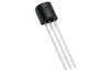 | STMicroelectronics | Silicon Controlled Rectifier, 0.8A I(T)RMS, 0.8A I(T), 100V V(DRM), 100V V(RRM), 1 Element, TO-92
RoHS : Compliant | | 13,035
|
DT06-08SB-P012
| TE Connectivity | Combination Line Connector, 8 Contact(s), Female, Crimp Terminal, Plug
RoHS : Compliant | | 11,066
|
P0153NL
| Pulse Electronics Corporation | General Purpose Inductor, 472uH, 20%, 1 Element, SMD, 5050
RoHS : Compliant | | 10,796
|
JT06RE-14-37P(014)
| Amphenol Corporation | MIL Series Connector, 37 Contact(s), Aluminum Alloy, Male, Crimp Terminal, Plug
RoHS : Not Compliant | | 9,612
|
TMP01FPZ
| Analog Devices Inc | Analog Voltage Output Sensor, 2.48V Min, 2.51V Max, 5Cel, Hybrid, Rectangular, 8 Pin, Through Hole Mount
RoHS : Compliant | | 9,329
|
2KBP01M-E4/51
| Vishay Intertechnologies | Bridge Rectifier Diode, 1 Phase, 2A, 100V V(RRM), Silicon
RoHS : Compliant | | 9,020
|
RI-TRP-REHP-01
| Texas Instruments | | | 7,964
|
CIMMA8MIJP01916$
| STMicroelectronics | | | 7,097
|
OP011EP
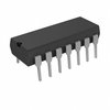 | Analog Devices Inc | Operational Amplifier, 4 Func, 800uV Offset-Max, BIPolar, PDIP14
RoHS : Not Compliant | | 6,878
|
OP01NT
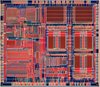 | Analog Devices Inc | Operational Amplifier, 1 Func, 1000uV Offset-Max, BIPolar
RoHS : Not Compliant | | 5,924
|
STEVAL-IFP016V2
| STMicroelectronics | | | 4,728
|
VN0300L-GP014
| Microchip Technology Inc | Small Signal Field-Effect Transistor, 0.64A I(D), 30V, 1-Element, N-Channel, Silicon, Metal-oxide Semiconductor FET, TO-92
RoHS : Compliant | | 525
|
L18P015S12
| Tamura Corporation of America | Sensor/Transducer
RoHS : Compliant | | 276
|


 Polish ▼
 English
 Chinese
 German
 Japanese
 Russian
 Korean
 Spanish
 French
 Italian
 Portuguese
 Vietnamese
 Indian
 Mexican
 British
 New Zealand