|
Zakładka z wyszukiwarką danych komponentów |
|
|
Zakładka z wyszukiwarką danych komponentów |
|
AD5544ACPZ-1-R2 Arkusz danych(PDF) 19 Page - Analog Devices |
|
|
|||||||||||||||||||||||||||||
AD5544ACPZ-1-R2 Arkusz danych(HTML) 19 Page - Analog Devices |
|
|
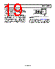
19 / 24 page  Data Sheet AD5544/AD5554 Rev. H | Page 19 of 24 LAYOUT AND POWER SUPPLY BYPASSING It is good practice to employ a compact, minimum lead length layout design. The leads to the input should be as direct as possible with a minimum conductor length. Ground paths should have low resistance and low inductance. Similarly, it is good practice to bypass the power supplies with quality capacitors for optimum stability. Supply leads to the device should be bypassed with 0.01 μF to 0.1 μF disc or chip ceramic capacitors. Low ESR 1 μF to 10 μF tantalum or electrolytic capaci- tors should also be applied at VDD to minimize any transient disturbance and filter any low frequency ripple (see Figure 26). Users should not apply switching regulators for VDD due to the power supply rejection ratio (PSRR) degradation over frequency. AGNDX VSS DGND AD5544/AD5554 VDD C3 10µF + C1 0.1µF C4 10µF C2 0.1µF VSS VDD Figure 26. Power Supply Bypassing and Grounding Connection GROUNDING The DGND and AGNDx pins of the AD5544/AD5554 serve as digital and analog ground references. To minimize the digital ground bounce, the DGND terminal should be joined remotely at a single point to the analog ground plane (see Figure 26). |
|
|
Link URL |
| Czy Alldatasheet okazała się pomocna? [ DONATE ] |
O Alldatasheet | Reklama | Kontakt | Polityka prywatności | Link do karty katalogowej | Linki | Lista producentów All Rights Reserved©Alldatasheet.com |
| Russian : Alldatasheetru.com | Korean : Alldatasheet.co.kr | Spanish : Alldatasheet.es | French : Alldatasheet.fr | Italian : Alldatasheetit.com Portuguese : Alldatasheetpt.com | Polish : Alldatasheet.pl | Vietnamese : Alldatasheet.vn Indian : Alldatasheet.in | Mexican : Alldatasheet.com.mx | British : Alldatasheet.co.uk | New Zealand : Alldatasheet.co.nz |
|
Family Site : ic2ic.com |
icmetro.com |
 Polish ▼
 English
 Chinese
 German
 Japanese
 Russian
 Korean
 Spanish
 French
 Italian
 Portuguese
 Polish
 Vietnamese
 Indian
 Mexican
 British
 New Zealand