|
Zakładka z wyszukiwarką danych komponentów |
|
|
Zakładka z wyszukiwarką danych komponentów |
|
LTC1422 Arkusz danych(PDF) 9 Page - Linear Technology |
|
|
|||||||||||||||||||||||||||||
LTC1422 Arkusz danych(HTML) 9 Page - Linear Technology |
|
|
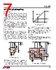
9 / 16 page  9 LTC1422 APPLICATIONS INFORMATION When the timer is off, the internal N-channel Q1 shorts the TIMER pin to ground. When the timer is turned on, a 2 µA current from VCC is connected to the TIMER pin and the voltage on the external capacitor C2 starts to ramp up with a slope given by: dV/dt = 2 µA/C2. When the voltage reaches the trip point (1.232V), the timer will be reset by pulling the TIMER pin back to ground. The timer period is given by: (1.232V • C2)/2 µA. For a 200ms delay, use a 0.33 µF capacitor. Electronic Circuit Breaker The LTC1422 features an electronic circuit breaker func- tion that protects against short circuits or excessive cur- rents on the supply. By placing a sense resistor between the supply input and SENSE pin, the circuit breaker will be tripped whenever the voltage across the sense resistor is greater than 50mV for more than 10 µs. When the circuit breaker trips, the GATE pin is immediately pulled to ground and the external N-channel is quickly turned off. When the ON pin is cycled off for greater than 40 µs and then on as shown in Figure 7, time point 7, the circuit breaker is reset and another timing cycle is started. At the end of the timer cycle (time point 8), the charge pump will turn on again. If the circuit breaker feature is not required, the SENSE pin should be shorted to VCC. If more than 10 µs of response time is needed to reject supply noise, an external resistor and capacitor can be added to the sense circuit as shown in Figure 8. Connection Sense with ON Pin The ON pin can be used to sense board connection to the backplane as shown in Figure 9. Using staggered connection pins, ground mates first to discharge any static build up on the board, followed by the VCC connection and all other pins. When VCC makes connection, the bases of transistors Q3 and Q4 are pulled high turning them on and pulling the ON pin to ground. When the base connector pins of Q3 and Q4 finally mate to the backplane, the bases are shorted to ground. This turns off Q3 and Q4 and allows the ON pin to pull high and start a power-up cycle. The base connection pins of Q3 and Q4 should be located at opposite ends of the connector RESET VOUT GATE 1422 F07 TIMER ON VCC – VSENSE VCC 1 2 3 4 5 6 7 8 9 10 because most people will rock the board back and forth to get it seated properly. A software-initiated power-down cycle can be started by momentarily turning on transistor Q2, which will pull the ON pin to ground. If the ON pin is held low for greater than 40 µs, the GATE pin is pulled to ground. If the low pulse on the ON pin is less than 15 µs, a soft reset is generated. Hot Swapping Two Supplies With two external pass transistors, the LTC1422 can switch two supplies. In some cases, it is necessary to bring up the dominant supply first during power-up and ramp it down last during the power-down phase. The circuit in Figure 10 shows how to program two different delays for the pass transistors. The 5V supply is powered up first. R1 Figure 7. Current Fault Timing SENSE 7 VCC 8 GATE LTC1422 6 C1 1422 F08 Q1 R1 RF CF R2 Figure 8. Extending the Short-Circuit Protection Delay |
|
|
Link URL |
| Czy Alldatasheet okazała się pomocna? [ DONATE ] |
O Alldatasheet | Reklama | Kontakt | Polityka prywatności | Link do karty katalogowej | Linki | Lista producentów All Rights Reserved©Alldatasheet.com |
| Russian : Alldatasheetru.com | Korean : Alldatasheet.co.kr | Spanish : Alldatasheet.es | French : Alldatasheet.fr | Italian : Alldatasheetit.com Portuguese : Alldatasheetpt.com | Polish : Alldatasheet.pl | Vietnamese : Alldatasheet.vn Indian : Alldatasheet.in | Mexican : Alldatasheet.com.mx | British : Alldatasheet.co.uk | New Zealand : Alldatasheet.co.nz |
|
Family Site : ic2ic.com |
icmetro.com |
 Polish ▼
 English
 Chinese
 German
 Japanese
 Russian
 Korean
 Spanish
 French
 Italian
 Portuguese
 Polish
 Vietnamese
 Indian
 Mexican
 British
 New Zealand