|
Zakładka z wyszukiwarką danych komponentów |
|
|
Zakładka z wyszukiwarką danych komponentów |
|
SP6648LED Arkusz danych(PDF) 2 Page - Sipex Corporation |
|
|
|||||||||||||||||||||||||||||
SP6648LED Arkusz danych(HTML) 2 Page - Sipex Corporation |
|
|
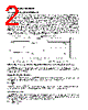
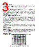
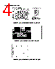
2 / 5 page  USING THE EVALUATION BOARD 1) Powering Up the SP6648LED Circuit The SP6648LED Evaluation Board can be powered from inputs from a +1.8V to +3.2V power supply or from 2 alkaline cells. Connect with short leads directly to the “VIN” and “GND” posts. Plug the 1W LumiLED between the “VOUT” and “REF” posts. Unlike other boost regulators, the part has self-protection feature. It will not be damaged when the output is open as long as there is a low resistance from FB to GND. As shown in Figures 1 and 2, if the board is powered up before the LumiLED is plugged in, the circuit will bring the Feedback pin to 0V and the SP6648 has a feature to set the output voltage to be 3.3V. Once the LumiLED is plugged in, the Feedback pin will go up to 1.25V and begin to regulate. The output voltage will go from 3.3V to 3.68V (=VF+0.61V) accordingly (as shown in Fig. 1), where VF is the forward voltage of the LumiLED. When the LumiLED is open, the Feedback pin voltage will go to 0V and the output voltage will go to 3.3V which will protect the part (as shown in Fig 2). Fig 1. Plug in the LumiLED Fig. 2. Unplug the LumiLED 2) Using the J1 Jumper: Enabling the SP6648 Output and using the Shutdown Mode The SP6648 output will be enabled if the J1 Jumper is in the top or pin 1 to 2 position. If J1 is in the pin 2 to 3 position, the Shutdown pin is brought to GND, which puts the SP6648 in the low quiescent Shutdown Mode. 3) Selecting the Bias Resistor In the white LEDs application, the SP6648 is generally programmed as a current source. The bias resistor is used to set the operating current of the white LED as equation F REF b I V R = where VREF is around 0.61V, IF is the operating current of the Lumiled. To set the operating current to be about 350mA, Rb is selected as 1.8 Ohm as shown in the schematic. 4) Vout Programming The SP6648 can be programmed as either a voltage source or a current source. To program the SP6648 as voltage source, the SP6648 requires 2 feedback resistors R6 & R7 to control the output voltage. To set Vout in the voltage mode, use the equation: 7 out 6 R 1 61 . 0 V R • − = VOUT VOUT VREF VREF |
|
|
Link URL |
| Czy Alldatasheet okazała się pomocna? [ DONATE ] |
O Alldatasheet | Reklama | Kontakt | Polityka prywatności | Link do karty katalogowej | Linki | Lista producentów All Rights Reserved©Alldatasheet.com |
| Russian : Alldatasheetru.com | Korean : Alldatasheet.co.kr | Spanish : Alldatasheet.es | French : Alldatasheet.fr | Italian : Alldatasheetit.com Portuguese : Alldatasheetpt.com | Polish : Alldatasheet.pl | Vietnamese : Alldatasheet.vn Indian : Alldatasheet.in | Mexican : Alldatasheet.com.mx | British : Alldatasheet.co.uk | New Zealand : Alldatasheet.co.nz |
|
Family Site : ic2ic.com |
icmetro.com |
 Polish ▼
 English
 Chinese
 German
 Japanese
 Russian
 Korean
 Spanish
 French
 Italian
 Portuguese
 Polish
 Vietnamese
 Indian
 Mexican
 British
 New Zealand