|
Zakładka z wyszukiwarką danych komponentów |
|
|
Zakładka z wyszukiwarką danych komponentów |
|
SP6648LED Arkusz danych(PDF) 3 Page - Sipex Corporation |
|
|
|||||||||||||||||||||||||||||
SP6648LED Arkusz danych(HTML) 3 Page - Sipex Corporation |
|
|
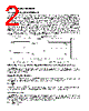
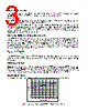
3 / 5 page  5) Using the Rlim Function The peak inductor current, IPEAK, is programmed externally by the RLIM resistor connected between the RLIM pin and GND. The peak inductor current is defined by: IPEAK = 1400/RLIM The SP6648 datasheet specifications for RLIM give a range of 1.87K to 4K ohms. Using the IPEAK equation above gives an IPEAK range of 350 to 750mA. The saturation current specified for the inductor needs to be greater then the peak current to avoid saturating the inductor, which would result in a loss in efficiency and could damage the inductor. The SP6648 evaluation board uses a Rlim value of 1.87K for an Ipeak = 750mA to allow the circuit to deliver up to 180mA for 1.3V input and 400mA for 2.6V input. Other values could be selected using the above relationships. 6) Using the LBON - Low Battery Output Function The SP6648 will regulate the output current until the input battery is completely discharged. To provide an early low battery warning, the Low Battery Output function of the SP6648 switching regulator can be used. LBON is programmed externally by the R1 and R2 resistor divider connected between VIN, the LBI input pin and GND. When the LBI comparator falling threshold of 0.61V is reached, D1 switches on, indicating low battery condition. Low battery detect trip point can be calculated by the following formula: 2 2 1 LOWBAT R R R 61 . 0 V + ⋅ = The SP6648 evaluation board R1 & R2 resistors have been set to trip for a falling battery threshold of about 2.0V. Using this relationship, other low battery threshold values can be set by the user. 7) Brightness Control One approach to control LED brightness is to apply a PWM signal to the SHDN input of the SP6648. In this case, the output current will be equal to the product of 350mA and the average duty cycle at the SHDN pin. An additional 10K potentiometer (R5) may also be used for dimming LED. LED current is varied by the potentiometer between almost zero and full 350mA. POWER SUPPLY DATA For the standard evaluation board, The efficiency curve is shown in the figure below. 60 65 70 75 80 85 90 95 100 1.8 2.0 2.2 2.4 2.6 2.8 3.0 3.2 Battery Voltage (V) Fig.3 Efficiency curve of the SP6648LED evaluation board |
|
|
Link URL |
| Czy Alldatasheet okazała się pomocna? [ DONATE ] |
O Alldatasheet | Reklama | Kontakt | Polityka prywatności | Link do karty katalogowej | Linki | Lista producentów All Rights Reserved©Alldatasheet.com |
| Russian : Alldatasheetru.com | Korean : Alldatasheet.co.kr | Spanish : Alldatasheet.es | French : Alldatasheet.fr | Italian : Alldatasheetit.com Portuguese : Alldatasheetpt.com | Polish : Alldatasheet.pl | Vietnamese : Alldatasheet.vn Indian : Alldatasheet.in | Mexican : Alldatasheet.com.mx | British : Alldatasheet.co.uk | New Zealand : Alldatasheet.co.nz |
|
Family Site : ic2ic.com |
icmetro.com |
 Polish ▼
 English
 Chinese
 German
 Japanese
 Russian
 Korean
 Spanish
 French
 Italian
 Portuguese
 Polish
 Vietnamese
 Indian
 Mexican
 British
 New Zealand