|
Zakładka z wyszukiwarką danych komponentów |
|
|
Zakładka z wyszukiwarką danych komponentów |
|
SC1403 Arkusz danych(PDF) 9 Page - Semtech Corporation |
|
|
|||||||||||||||||||||||||||||
SC1403 Arkusz danych(HTML) 9 Page - Semtech Corporation |
|
|
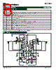
9 / 30 page  9 2002 Semtech Corp. www.semtech.com SC1403 POWER MANAGEMENT PRELIMINARY Functional Information Detailed Description The SC1403 is a versatile multiple-output power supply controller designed to power battery operated systems. Out of phase switching design is adopted to improve signal quality and reduce input RMS current, therefore reducing size of input filter inductor and capacitors. The SC1403 provides synchronous rectified buck control in fixed frequency forced-continuous mode and hysteretic PSAVE mode for two switching power supplies over a wide load range. The two switchers have on-chip preset output voltage of 5.0V and 3.3V. An external resistor divider can be used to set the switcher outputs from 2.5V to 5.5V. The control and fault monitoring circuitry associated with each PWM controller includes digital softstart, turn-on sequencing, voltage error amplifier with built-in slope compensation, pulse width modulator, power save, over-current, over-voltage and under-voltage fault protection. One linear regulator and a precision reference voltage are also provided by the SC1403. The 5V/50mA linear regulator takes input from the battery to power the gate drivers, however to improve efficiency, the 5V switcher output is used instead when available. Semtech’s proprietary Virtual Current SenseTM provides greater advantages in the aspect of stability and signal to noise ratio than the conventional current sense method. PWM control There are two separate PWM control blocks for the 3V and 5V switchers. They are out-of-phase with each other. The interleaved topology offers greater advantage over in-phase solutions. It reduces steady state input filter requirements by reducing current drawn from the filter capacitors. To avoid both switchers switching at the same instance, there is a built-in delay between the on-time of the 3.3V switcher and 5V switcher, the amount of which depends on the input voltage (see Out-of-Phase Switching). The PWM provides two modes of control over the entire load range. The SC1403 operates in forced continuous conduction mode as a fixed frequency peak current mode controller with falling edge modulation. Current sense is done differently than that in the conventional peak current mode control. Semtech’s proprietary Virtual Current SenseTM emulates the necessary inductor current information for proper functioning of the IC. In order to accommodate a wide range of output filters, a COMP pin is also available for compensating the error amplifier externally. A nominal gain of 18 is used in the error amplifier to further improve the system loop gain response and the output transient behavior. When the switcher is operating in continuous conduction mode, the high- side MOSFET is turned on at the beginning of each switching cycle. It is turned off when the desired duty cycle is reached. Active shoot- through protection delays the turn-on of the lower MOSFET until the phase node drops below 2.5V. The low-side MOSFET remains on until the beginning of the next switching cycle. Again, active shoot-through protection ensures that the gate to the low-side MOSFET has dropped low before the high-side MOSFET is turned on. Under light load conditions when the PSAVE pin is low, the SC1403 operates as a hysteretic controller in the discontinuous conduction mode to reduce its switching frequency and switching bias current. The switching of the output MOSFET does not depend on a given oscillator frequency, but on the hysteretic FB trip voltage set around the reference. When entering PSAVE mode, if the minimum (valley) inductor current measured across the CSH and CSL pins is below the PSAVE threshold for four switching cycles, the virtual current sensing circuitry is shutdown and PWM switches from forced continuous to hysteretic mode. If the minimum (valley) inductor current is above the threshold for four switching cycles, PWM control changes from hysteretic to forced continuous mode. The SC1403 provides built-in hysteresis to prevent chattering between the two modes of operation. Gate Drive / Control The gate drivers on the SC1403 are designed to switch large MOSFETs up to 350KHz. The high-side gate driver is required to drive the gates of high-side MOSFET above the V+ input. The supply for the gate drivers is generated by charging a boostrap capacitor from the VL supply when the low-side driver is on. Monitoring circuitry ensures that the bootstrap capacitor is charged when coming out of shutdown or fault conditions where the bootstrap capacitor may be depleted. In continuous conduction mode, the low-side driver output that controls the synchronous rectifier in the power stage is on when the high-side driver is off. Under light load conditions when PSAVE pin is low, the inductor ripple current will approach the point where it reverses polarity. This is detected by the low-side driver control and the synchronous rectifier is turned off before the current reverses, preventing energy drain from the output. The low-side driver operation is also affected by various fault conditions as described in the Fault Protection section. Internal Bias Supply The VL linear regulator provides a 5V output that is used to power the gate drivers, 2.5V reference and internal control section of the SC1403. The regulator is capable of supplying up to 50mA (in- cluding MOSFET gate charge current). The VL pin should be by- passed to GND with 4.7uF to supply the peak current require- ments of the gate driver outputs. The regulator receives its input power from the V+ battery input. Efficiency is improved by provid- ing a boot-strapping mode for the VL bias. When the 5V SMPS output voltage reaches 5V, internal circuitry detects this condition and turns on a PMOS pass device between CSL5 and VL. The internal VL regulator is then disabled and the VL bias is provided by the high efficiency switcher. The REF output is accurate to +/- 2% over temperature. It is capable of delivering 5mA max and should be bypassed with 1uF minimum capacitor. Loading the REF pin will reduce the REF voltage slightly. |
|
Link URL |
| Czy Alldatasheet okazała się pomocna? [ DONATE ] |
O Alldatasheet | Reklama | Kontakt | Polityka prywatności | Link do karty katalogowej | Linki | Lista producentów All Rights Reserved©Alldatasheet.com |
| Russian : Alldatasheetru.com | Korean : Alldatasheet.co.kr | Spanish : Alldatasheet.es | French : Alldatasheet.fr | Italian : Alldatasheetit.com Portuguese : Alldatasheetpt.com | Polish : Alldatasheet.pl | Vietnamese : Alldatasheet.vn Indian : Alldatasheet.in | Mexican : Alldatasheet.com.mx | British : Alldatasheet.co.uk | New Zealand : Alldatasheet.co.nz |
|
Family Site : ic2ic.com |
icmetro.com |
 Polish ▼
 English
 Chinese
 German
 Japanese
 Russian
 Korean
 Spanish
 French
 Italian
 Portuguese
 Polish
 Vietnamese
 Indian
 Mexican
 British
 New Zealand