 |
Zakładka z wyszukiwarką danych komponentów |
|
|
Zakładka z wyszukiwarką danych komponentów |
|
The question interval is too short.
Please try again in a few seconds.

Hello, Please ask a question about AN-733 Datasheet
# Example questions:
➢ What are the primary drawbacks of using series resistor compensation for stabilizing an op amp driving a capacitive load?
➢ The document details a method for generating square waveforms. what component values primarily determine the oscillation frequency (fo) in this method?
➢ How does a snubber network differ from series resistor compensation in terms of its impact on output swing and gain accuracy, according to the document?
| Part No. | AN-733 |
| Manufacturer | AD |
| Size | 631 Kbytes |
| Pages | 4 pages |
| Description | Universal Precision Op Amp Evaluation Board in MSOP Package |

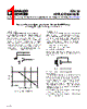
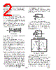
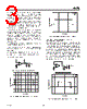
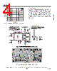

1. Overview & Purpose of the Document
️· Document Type: Application Note (likely a technical guide) focusing on using the Analog Devices PRA OPAMP evaluation board.
️· Purpose: Provides examples of how to use the evaluation board for common amplifier applications, including:
- Generating square waveforms (bistable multivibrator)
- Implementing current-to-voltage converters
- Providing external compensation techniques (series resistor compensation)
- Stabilizing amplifiers driving capacitive loads (snubber networks)
2. Bistable Multivibrator and Square Wave Generation
️· Principle: Uses a bistable multivibrator configuration to generate a square waveform.
️· Mechanism: The amplifier switches between two stable states. Capacitor charging/discharging determines switching frequency.
️· Frequency Control: Frequency is determined by external components (R7, C9) and the amplifier’s supply voltages (L+). Changing the amplifier supply voltages proportionally changes the transition times and overall frequency.
️· Formula for Oscillation Frequency:
- `T = 2R7 * C9 * ln((1 + B) / (1 – B))`
- `fO = 1/T`
- Where:
■ `T` = Period of oscillation
■ `fO` = Oscillation frequency
■ `R7` = Resistor value
■ `C9` = Capacitor value
■ `B` = Feedback factor (calculated as `R4 / (R4 + R9)`)
3. Current-to-Voltage Converter
️· Operation: Input current is fed directly into the amplifier's summing node. The amplifier output voltage changes to match the input current.
️· Scale Factor: The conversion factor is `R7` volts per amp.
️· Error Consideration: The amplifier’s input bias current (I BIAS) contributes to error in the conversion.
4. External Compensation Techniques
️· Series Resistor Compensation: Used to stabilize amplifiers when driving capacitive loads. A series resistor isolates the amplifier's output and feedback network.
- Typical Resistance Values: 5Ω to 50Ω.
- Drawbacks: Can reduce gain accuracy and introduce distortion.
5. Snubber Networks
️· Purpose: Stabilize amplifiers driving capacitive loads.
️· Advantages:
- Maintains output swing.
- Does not degrade gain accuracy or introduce distortion.
️· Implementation: Requires experimental determination of optimal resistor (R) and capacitor (C) values.
6. Differential Amplifier Considerations
️· CMRR (Common-Mode Rejection Ratio): Key performance metric
️· Impact of Resistor Mismatch: Inaccurate resistor values degrade CMRR.
️· Optimization Strategies:
- Use high-gain amplifiers with low input bias current (e.g., AD8551, AD8571, AD8603, AD8605).
- Select closely matched resistors.
- Increase amplifier gain.
7. Evaluation Board Specifics (PRA OPAMP Evaluation Board)
️· Component Naming Convention: The document refers to specific component names and designations.
️· Board Layout: Figure 13 shows the board layout.
Key Takeaways & Design Considerations
️· Component Selection: Careful selection of resistors and capacitors is critical for achieving desired performance and stability.
️· Bias Current: The amplifier's input bias current can introduce errors in precision circuits.
️· Stability: External compensation techniques (series resistors, snubbers) are often necessary to ensure stable operation when driving capacitive loads.
️· Resistor Tolerance: For differential amplifiers, close resistor tolerance is important for achieving a high CMRR.
1. Overview & Purpose of the Document
️· Document Type: Application Note (likely a technical guide) focusing on using the Analog Devices PRA OPAMP evaluation board.
️· Purpose: Provides examples of how to use the evaluation board for common amplifier applications, including:
- Generating square waveforms (bistable multivibrator)
- Implementing current-to-voltage converters
- Providing external compensation techniques (series resistor compensation)
- Stabilizing amplifiers driving capacitive loads (snubber networks)
2. Bistable Multivibrator and Square Wave Generation
️· Principle: Uses a bistable multivibrator configuration to generate a square waveform.
️· Mechanism: The amplifier switches between two stable states. Capacitor charging/discharging determines switching frequency.
️· Frequency Control: Frequency is determined by external components (R7, C9) and the amplifier’s supply voltages (L+). Changing the amplifier supply voltages proportionally changes the transition times and overall frequency.
️· Formula for Oscillation Frequency:
- `T = 2R7 * C9 * ln((1 + B) / (1 – B))`
- `fO = 1/T`
- Where:
■ `T` = Period of oscillation
■ `fO` = Oscillation frequency
■ `R7` = Resistor value
■ `C9` = Capacitor value
■ `B` = Feedback factor (calculated as `R4 / (R4 + R9)`)
3. Current-to-Voltage Converter
️· Operation: Input current is fed directly into the amplifier's summing node. The amplifier output voltage changes to match the input current.
️· Scale Factor: The conversion factor is `R7` volts per amp.
️· Error Consideration: The amplifier’s input bias current (I BIAS) contributes to error in the conversion.
4. External Compensation Techniques
️· Series Resistor Compensation: Used to stabilize amplifiers when driving capacitive loads. A series resistor isolates the amplifier's output and feedback network.
- Typical Resistance Values: 5Ω to 50Ω.
- Drawbacks: Can reduce gain accuracy and introduce distortion.
5. Snubber Networks
️· Purpose: Stabilize amplifiers driving capacitive loads.
️· Advantages:
- Maintains output swing.
- Does not degrade gain accuracy or introduce distortion.
️· Implementation: Requires experimental determination of optimal resistor (R) and capacitor (C) values.
6. Differential Amplifier Considerations
️· CMRR (Common-Mode Rejection Ratio): Key performance metric
️· Impact of Resistor Mismatch: Inaccurate resistor values degrade CMRR.
️· Optimization Strategies:
- Use high-gain amplifiers with low input bias current (e.g., AD8551, AD8571, AD8603, AD8605).
- Select closely matched resistors.
- Increase amplifier gain.
7. Evaluation Board Specifics (PRA OPAMP Evaluation Board)
️· Component Naming Convention: The document refers to specific component names and designations.
️· Board Layout: Figure 13 shows the board layout.
Key Takeaways & Design Considerations
️· Component Selection: Careful selection of resistors and capacitors is critical for achieving desired performance and stability.
️· Bias Current: The amplifier's input bias current can introduce errors in precision circuits.
️· Stability: External compensation techniques (series resistors, snubbers) are often necessary to ensure stable operation when driving capacitive loads.
️· Resistor Tolerance: For differential amplifiers, close resistor tolerance is important for achieving a high CMRR.
| Part No. | AN-733 |
| Manufacturer | AD |
| Size | 631 Kbytes |
| Pages | 4 pages |
| Description | Universal Precision Op Amp Evaluation Board in MSOP Package |
| Czy Alldatasheet okazała się pomocna? [ DONATE ] |
O Alldatasheet | Reklama | Kontakt | Polityka prywatności | Link do karty katalogowej | Linki | Lista producentów All Rights Reserved©Alldatasheet.com |
| Russian : Alldatasheetru.com | Korean : Alldatasheet.co.kr | Spanish : Alldatasheet.es | French : Alldatasheet.fr | Italian : Alldatasheetit.com Portuguese : Alldatasheetpt.com | Polish : Alldatasheet.pl | Vietnamese : Alldatasheet.vn Indian : Alldatasheet.in | Mexican : Alldatasheet.com.mx | British : Alldatasheet.co.uk | New Zealand : Alldatasheet.co.nz |
|
Family Site : ic2ic.com |
icmetro.com |
 Polish ▼
  English
 Chinese
 German
 Japanese
 Russian
 Korean
 Spanish
 French
 Italian
 Portuguese
 Vietnamese
 Indian
 Mexican
 British
 New Zealand