|
Zakładka z wyszukiwarką danych komponentów |
|
|
Zakładka z wyszukiwarką danych komponentów |
|
AN-733 Arkusz danych(PDF) 1 Page - Analog Devices |
|
|
|||||||||||||||||||||||||||||
AN-733 Arkusz danych(HTML) 1 Page - Analog Devices |
|
|
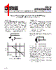
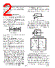
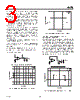
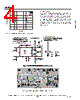
1 / 4 page  AN-733 APPLICATION NOTE One Technology Way • P.O. Box 9106 • Norwood, MA 02062-9106 • Tel TT : 781/329-4700 • Fax: 781/326-8703 • www.analog.com INTRODUCTION The EVAL-PRAOPAMP-1RM is an evaluation board which accommodates single op amps in MSOP packages. It is meant to provide the user with multiple choices and extensive flexibility for different application circuits and configurations. This board is not intended to be used with high frequency components or high speed amplifiers. However, it provides the user with many combinations for various circuit types, including active filters, differential amplifiers, and external frequency compensation circuits. A few examples of application circuits are given in this application note. ���� �� �� �� �� ��� �������� ��������� � ��� � �� �� �� ��� ���� ����� ������ �� �� ����� � ��� Figure 1. Simple Low-Pass Filter Universal Precision Op Amp Evaluation Board in MSOP Package by Giampaolo Marino, Soufiane Bendaoud, and Steve Ranta LOW-PASS FILTER Figure 1 is a typical representation of a first-order low- pass filter. This circuit has a 6 dB per octave roll-off after a close-loop –3 dB point defined by fC. Gain below this frequency is defined as the magnitude of R7 to R2. The circuit might be considered as an ac integrator for frequencies well above fC; however, the time domain response is that of a single RC, rather than an integral. fC = 1/(2 R7 C7); –3 dB frequency fL = 1/(2 R2 C7); unity gain frequency Acl = –(R7/R2); close loop gain R6 should be chosen equal to the parallel combination between R7 and R2 in order to minimize errors due to bias currents. ���� �� �� �� �� ���� ���� Figure 2. Difference Amplifier DIFFERENCE AMPLIFIER AND PERFORMANCE OPTIMIZATION Figure 2 shows an op amp configured as a difference amplifier. The difference amplifier is the complement of the summing amplifier, and allows the subtraction of two voltages or the cancellation of a signal common to both inputs. The circuit shown in Figure 2 is useful as a computational amplifier in making a differential to single-ended conversion or in rejecting a common- mode signal. The output voltage VOUT is comprised of two separate components: 1. A component VOUT1 due to VIN1 acting alone (VIN2 short circuited to ground.) 2. A component VOUT2 due to VIN2 acting alone (VIN1 short circuited to ground.) REV. A |
Podobny numer części - AN-733 |
|
Podobny opis - AN-733 |
|
|
|
Link URL |
| Czy Alldatasheet okazała się pomocna? [ DONATE ] |
O Alldatasheet | Reklama | Kontakt | Polityka prywatności | Link do karty katalogowej | Linki | Lista producentów All Rights Reserved©Alldatasheet.com |
| Russian : Alldatasheetru.com | Korean : Alldatasheet.co.kr | Spanish : Alldatasheet.es | French : Alldatasheet.fr | Italian : Alldatasheetit.com Portuguese : Alldatasheetpt.com | Polish : Alldatasheet.pl | Vietnamese : Alldatasheet.vn Indian : Alldatasheet.in | Mexican : Alldatasheet.com.mx | British : Alldatasheet.co.uk | New Zealand : Alldatasheet.co.nz |
|
Family Site : ic2ic.com |
icmetro.com |
 Polish ▼
 English
 Chinese
 German
 Japanese
 Russian
 Korean
 Spanish
 French
 Italian
 Portuguese
 Polish
 Vietnamese
 Indian
 Mexican
 British
 New Zealand