 |
Zakładka z wyszukiwarką danych komponentów |
|
|
Zakładka z wyszukiwarką danych komponentów |
|
The question interval is too short.
Please try again in a few seconds.

Hello, Please ask a question about IRF9392PBF_15 Datasheet
# Example questions:
➢ What test circuit is depicted in figure 17a, and what is its purpose?
➢ What is the relationship between the rectangular pulse duration (t1) and the maximum effective transient thermal impedance?
➢ What does 'zthja' represent?
| Part No. | IRF9392PBF_15 |
| Manufacturer | IRF |
| Size | 288 Kbytes |
| Pages | 8 pages |
| Description | Industry-Standard SO8 Package |


1. Device Identification and General Characteristics
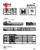
️· Product Type: Power MOSFET (likely P-Channel, based on some of the diagrams).
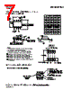
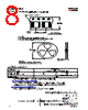
️· Datasheet Structure: The document is highly detailed, with numerous graphs, tables, and circuit diagrams illustrating various performance metrics.
2. Electrical Characteristics (Key Metrics & How They's Presented)
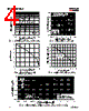
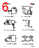
️· Gate Charge (Qg): Figures 17a & 17b depict the test circuit and waveform for measuring gate charge. Qg is a critical parameter for switching speed. Lower Qg means faster switching.
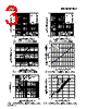
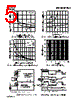
️· Drain-Source Voltage (Vds) vs. Drain Current (Id): Numerous graphs (e.g., Fig. 12) show how the drain current changes with the drain-source voltage at different gate voltages. This helps determine the device's ability to handle current.
️· On-Resistance (Rds(on)): A key parameter determining power dissipation. Lower Rds(on) is better. Figs. 12 and 13 show relationships between Rds(on), gate voltage, and drain current.
️· Gate-Source Voltage (Vgs): The voltage applied to the gate to control the MOSFET.
️· Drain Current (Id): The current flowing from the drain to the source.
️· Avalanche Energy (Eav): Fig. 14 represents this, illustrating the maximum energy the device can handle under avalanche conditions. Important for certain applications.
️· Switching Times (tr, td(on), td(off), tf): Fig. 19 shows a test circuit and waveform. These times relate to how quickly the MOSFET turns on and off, affecting efficiency and noise.
️· Dynamic Input Capacitance: Data presented throughout regarding capacitances within the device.
️· Thermal Characteristics: Data provided on thermal resistance (Rth), junction temperature (Tj), and thermal impedance.
3. Circuit Diagrams & Test Setups
️· Fig. 17a & 17b (Gate Charge Test Circuit & Waveform): Standard test setup for measuring gate charge.
️· Fig. 18a & 18b (Unclamped Inductive Test Circuit & Waveform): Used to assess the device’s behavior under inductive loads, which can create voltage spikes.
️· Fig. 19a & 19b (Switching Time Test Circuit & Waveform): Standard circuit and waveform for measuring switching times.
️· Fig. 3 (Typical Electrical Characteristics): A collection of key performance indicators.
4. Applications & Considerations
️· Inductive Loads: The unclamped inductive test is vital for applications with inductive loads (motors, relays, etc.) as these loads can generate voltage spikes that can damage the MOSFET.
️· Switching Speed: Switching times are critical for high-frequency switching applications (DC-DC converters, PWM controllers).
️· Thermal Management: Understanding the thermal resistance (Rth) is vital to prevent overheating and ensure reliable operation.
️· Avalanche Capability: The avalanche energy specification is important if the MOSFET might operate under avalanche conditions.
5. Specific Data Points Highlighted in Tables
(Because I can't recreate the massive number of tables, I'm picking out *examples* from the scans – this will give you an idea of the type of data.)
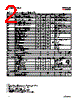
️· Summary of parameters and values Various parameters and their corresponding values listed with specific units and test conditions.
️· Data Tables for Electrical and Thermal Characteristics: Tables list values for things like Vds(max), Id(max), Rds(on) at different Vgs values, thermal resistance values, etc.
️· Test Conditions: The datasheet will always specify the test conditions under which the data was obtained (Vgs, temperature, etc.).
SUMMARY:
This datasheet provides an incredibly detailed specification for a P-Channel Power MOSFET. It is designed for applications requiring efficient switching and the ability to handle inductive loads. The data covers electrical characteristics (gate charge, on-resistance, leakage current), thermal characteristics, and switching performance. The user should carefully review the test conditions and application notes to ensure the MOSFET is used within its specified limits. The included circuit diagrams illustrate how the device's performance is evaluated under various load conditions. The datasheet is geared towards engineers needing a thorough understanding of the MOSFET's behavior in a power electronics design.
1. Device Identification and General Characteristics
️· Product Type: Power MOSFET (likely P-Channel, based on some of the diagrams).
️· Datasheet Structure: The document is highly detailed, with numerous graphs, tables, and circuit diagrams illustrating various performance metrics.
2. Electrical Characteristics (Key Metrics & How They's Presented)
️· Gate Charge (Qg): Figures 17a & 17b depict the test circuit and waveform for measuring gate charge. Qg is a critical parameter for switching speed. Lower Qg means faster switching.
️· Drain-Source Voltage (Vds) vs. Drain Current (Id): Numerous graphs (e.g., Fig. 12) show how the drain current changes with the drain-source voltage at different gate voltages. This helps determine the device's ability to handle current.
️· On-Resistance (Rds(on)): A key parameter determining power dissipation. Lower Rds(on) is better. Figs. 12 and 13 show relationships between Rds(on), gate voltage, and drain current.
️· Gate-Source Voltage (Vgs): The voltage applied to the gate to control the MOSFET.
️· Drain Current (Id): The current flowing from the drain to the source.
️· Avalanche Energy (Eav): Fig. 14 represents this, illustrating the maximum energy the device can handle under avalanche conditions. Important for certain applications.
️· Switching Times (tr, td(on), td(off), tf): Fig. 19 shows a test circuit and waveform. These times relate to how quickly the MOSFET turns on and off, affecting efficiency and noise.
️· Dynamic Input Capacitance: Data presented throughout regarding capacitances within the device.
️· Thermal Characteristics: Data provided on thermal resistance (Rth), junction temperature (Tj), and thermal impedance.
3. Circuit Diagrams & Test Setups
️· Fig. 17a & 17b (Gate Charge Test Circuit & Waveform): Standard test setup for measuring gate charge.
️· Fig. 18a & 18b (Unclamped Inductive Test Circuit & Waveform): Used to assess the device’s behavior under inductive loads, which can create voltage spikes.
️· Fig. 19a & 19b (Switching Time Test Circuit & Waveform): Standard circuit and waveform for measuring switching times.
️· Fig. 3 (Typical Electrical Characteristics): A collection of key performance indicators.
4. Applications & Considerations
️· Inductive Loads: The unclamped inductive test is vital for applications with inductive loads (motors, relays, etc.) as these loads can generate voltage spikes that can damage the MOSFET.
️· Switching Speed: Switching times are critical for high-frequency switching applications (DC-DC converters, PWM controllers).
️· Thermal Management: Understanding the thermal resistance (Rth) is vital to prevent overheating and ensure reliable operation.
️· Avalanche Capability: The avalanche energy specification is important if the MOSFET might operate under avalanche conditions.
5. Specific Data Points Highlighted in Tables
(Because I can't recreate the massive number of tables, I'm picking out *examples* from the scans – this will give you an idea of the type of data.)
️· Summary of parameters and values Various parameters and their corresponding values listed with specific units and test conditions.
️· Data Tables for Electrical and Thermal Characteristics: Tables list values for things like Vds(max), Id(max), Rds(on) at different Vgs values, thermal resistance values, etc.
️· Test Conditions: The datasheet will always specify the test conditions under which the data was obtained (Vgs, temperature, etc.).
SUMMARY:
This datasheet provides an incredibly detailed specification for a P-Channel Power MOSFET. It is designed for applications requiring efficient switching and the ability to handle inductive loads. The data covers electrical characteristics (gate charge, on-resistance, leakage current), thermal characteristics, and switching performance. The user should carefully review the test conditions and application notes to ensure the MOSFET is used within its specified limits. The included circuit diagrams illustrate how the device's performance is evaluated under various load conditions. The datasheet is geared towards engineers needing a thorough understanding of the MOSFET's behavior in a power electronics design.
| Part No. | IRF9392PBF_15 |
| Manufacturer | IRF |
| Size | 288 Kbytes |
| Pages | 8 pages |
| Description | Industry-Standard SO8 Package |
| Czy Alldatasheet okazała się pomocna? [ DONATE ] |
O Alldatasheet | Reklama | Kontakt | Polityka prywatności | Link do karty katalogowej | Linki | Lista producentów All Rights Reserved©Alldatasheet.com |
| Russian : Alldatasheetru.com | Korean : Alldatasheet.co.kr | Spanish : Alldatasheet.es | French : Alldatasheet.fr | Italian : Alldatasheetit.com Portuguese : Alldatasheetpt.com | Polish : Alldatasheet.pl | Vietnamese : Alldatasheet.vn Indian : Alldatasheet.in | Mexican : Alldatasheet.com.mx | British : Alldatasheet.co.uk | New Zealand : Alldatasheet.co.nz |
|
Family Site : ic2ic.com |
icmetro.com |
 Polish ▼
  English
 Chinese
 German
 Japanese
 Russian
 Korean
 Spanish
 French
 Italian
 Portuguese
 Vietnamese
 Indian
 Mexican
 British
 New Zealand