|
Zakładka z wyszukiwarką danych komponentów |
|
|
Zakładka z wyszukiwarką danych komponentów |
|
FDC2114 Arkusz danych(PDF) 28 Page - TEXAS ADVANCED OPTOELECTRONIC SOLUTIONS |
|
|
|||||||||||||||||||||||||||||
FDC2114 Arkusz danych(HTML) 28 Page - TEXAS ADVANCED OPTOELECTRONIC SOLUTIONS |
|
|
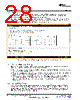
28 / 62 page  GUI Operation www.ti.com 3.5.2 Selecting the Clocking Source While the device contains an internal oscillator which requires fewer components in a system, it is recommended to use an external oscillator for precision applications. The EVM includes a 40MHz oscillator on-board, but an external off board signal can be used. To choose the oscillator source select one of the options in the “Reference Clock Source” section of the “Measurement Settings”. If using an external oscillator, enter the oscillation frequency so that the GUI correctly displays data measurements of frequency and capacitance. Figure 34. Selecting the External Oscillator and Entering its Frequency 3.5.3 Setting the Measurement Timings Determining the best timing settings for the device is largely dependent on the application and sensor design, but in general the following items should be considered • Each channel should have the maximum reference frequency possible. Most applications should have the channel Fref dividers set to one. • Settle count needs to be long enough, but increasing it arbitrary holds no value and only decreases the sampling rate. Reference the datasheet for calculating the optimal settle count. • Reference count has the largest effect on the accuracy of a measurement. Increasing the reference count leads to a more accurate measurement, but at the cost of decreased sampling rate. The effective number of bits for each channel is calculated in the table for each channel based on the reference count. 3.5.4 Using a Different Sensor When using a different sensor, several parameters could be changed. The sensor’s resonant frequency could be vastly different or a different sensor inductor could be used. If the resonant frequency of the sensor is less than 8.75MHz the F in select should be set to one. If the sensor frequency is greater than 8.75 MHz, F in select should be two. The sensor filter inductor for each channel should be updated to reflect to actual component value on the sensor. 28 FDC2114 and FDC2214 EVM User’s Guide SNOU138 – June 2015 Submit Documentation Feedback Copyright © 2015, Texas Instruments Incorporated |
|
Link URL |
| Czy Alldatasheet okazała się pomocna? [ DONATE ] |
O Alldatasheet | Reklama | Kontakt | Polityka prywatności | Link do karty katalogowej | Linki | Lista producentów All Rights Reserved©Alldatasheet.com |
| Russian : Alldatasheetru.com | Korean : Alldatasheet.co.kr | Spanish : Alldatasheet.es | French : Alldatasheet.fr | Italian : Alldatasheetit.com Portuguese : Alldatasheetpt.com | Polish : Alldatasheet.pl | Vietnamese : Alldatasheet.vn Indian : Alldatasheet.in | Mexican : Alldatasheet.com.mx | British : Alldatasheet.co.uk | New Zealand : Alldatasheet.co.nz |
|
Family Site : ic2ic.com |
icmetro.com |
 Polish ▼
 English
 Chinese
 German
 Japanese
 Russian
 Korean
 Spanish
 French
 Italian
 Portuguese
 Polish
 Vietnamese
 Indian
 Mexican
 British
 New Zealand