|
Zakładka z wyszukiwarką danych komponentów |
|
|
Zakładka z wyszukiwarką danych komponentów |
|
FDC2114 Arkusz danych(PDF) 31 Page - TEXAS ADVANCED OPTOELECTRONIC SOLUTIONS |
|
|
|||||||||||||||||||||||||||||
FDC2114 Arkusz danych(HTML) 31 Page - TEXAS ADVANCED OPTOELECTRONIC SOLUTIONS |
|
|
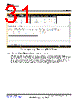
31 / 62 page  www.ti.com GUI Operation Figure 38. Updating Input Measurement Offset for FDC2114 3.5.5 Setting the Power Mode and Sensor Initialization Currents Most applications do not need maximum channel initialization currents and the low power sensor activation mode should be enabled. When low power sensor activation mode is enabled, the IDRIVE code determines how much current the device supplies to the sensor. To determine the optimal current drive setting, move the system target to its furthest distance from the sensor and click the “Detect iDriveInit with Auto-Amplitude Correction” button. This will take a measurement to determine an appropriate current setting. After the setting has been measured, the code value of I drive must be adjusted. 31 SNOU138 – June 2015 FDC2114 and FDC2214 EVM User’s Guide Submit Documentation Feedback Copyright © 2015, Texas Instruments Incorporated |
|
Link URL |
| Czy Alldatasheet okazała się pomocna? [ DONATE ] |
O Alldatasheet | Reklama | Kontakt | Polityka prywatności | Link do karty katalogowej | Linki | Lista producentów All Rights Reserved©Alldatasheet.com |
| Russian : Alldatasheetru.com | Korean : Alldatasheet.co.kr | Spanish : Alldatasheet.es | French : Alldatasheet.fr | Italian : Alldatasheetit.com Portuguese : Alldatasheetpt.com | Polish : Alldatasheet.pl | Vietnamese : Alldatasheet.vn Indian : Alldatasheet.in | Mexican : Alldatasheet.com.mx | British : Alldatasheet.co.uk | New Zealand : Alldatasheet.co.nz |
|
Family Site : ic2ic.com |
icmetro.com |
 Polish ▼
 English
 Chinese
 German
 Japanese
 Russian
 Korean
 Spanish
 French
 Italian
 Portuguese
 Polish
 Vietnamese
 Indian
 Mexican
 British
 New Zealand